About Atomic Designer V5
It all started with a simple idea.
Why are so many projects started from scratch? And how do we keep an overview of large projects? Can we do something to minimize dependencies so that reusability becomes possible? And why isn’t there something like schematic entry, as is common in electronics development?.
The idea dates back to 2012 and has been further developed over the years. The core of the concept consisted of:
- The use of graphical components: reusable and allowing multiple instances within the same project.
- Improved clarity through the use of pages, subpages, and subsystems.
- Writing embedded software in C directly within graphical blocks.
- The ability to connect graphical blocks via interfaces and wires.

Graphic components
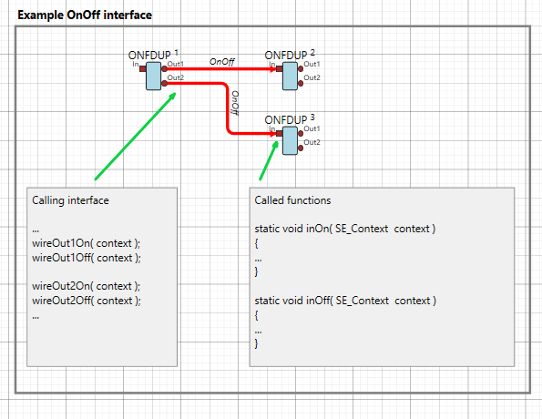
This image illustrates how two graphical blocks use interfaces to communicate.
In this example, we immediately see that the same component (ONFDUP) is used three times, so we allow multiple instances.
The interface call follows the naming convention:
wire <component socket> <interface function>(context);
For more details, see section About wires.
Variants
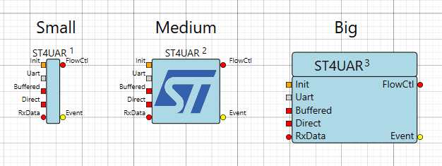
Components come in 3 variants.
Small
Medium
Big
The variant can be selected via the context menu
Sheets en Subsystems
For clarity, sheets can be created that contain components and even other sheets. A similar type to sheets is the subsystem.
The difference is that a sheet is part of a project and is unique to each project. A subsystem, on the other hand, is both a sheet and a component, and is stored as such among the components. This makes a subsystem reusable across multiple projects.
- Sheets are green
- Subsystems are green-blue
Example subsystem

Labels
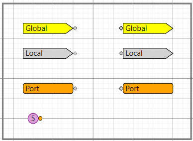
Labels can also be used. These include:
- Global labels – These are yellow and apply to the entire project.
- Local labels – These are grey and apply only within the current page.
- Port labels – These are orange and refer to a connection on the page’s symbol from within the page itself.
- Start labels – These are purple dots, used for initialization. The number inside determines the order of initialization.
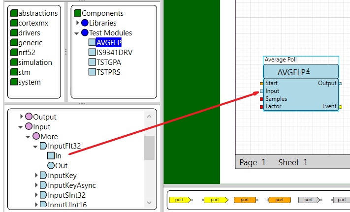
Component creation
Users can create their own components.
- There are different types: component, sheet, and subsystem.
- Interfaces can be added by dragging them from the interface list.
- The framework in which C-code can be written is automatically generated.
Components can only be created or modified in Edit mode. To enter Edit mode, hover over the component and select the option from the context menu.
For more details, see section How do I create a component