Since the use of the wiring concept is something unfamiliar, here is a brief description.
The concept of wiring is borrowed from electronic schematic design. Components are interconnected via copper traces. This way, one component can pass information to another component. Software wiring is similar. Through interface sockets and the wiring between them, information is exchanged.
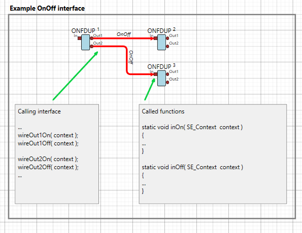
Let’s take a look at an example in the picture next to this.
Interface sockets can only be connected with a wire if the interface type is the same. In this case, the OnOff interface is used on both sides.
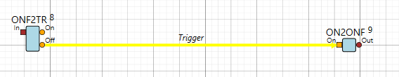
Wires can be created by dragging them from an output interface (circle) to an input interface (square).
The wiring automatically snaps to the input interface when the mouse comes close
The OnOff interface contains two functions: On and Off. The caller can use both functions if needed.
Wires exist only as a visual abstraction; in code, they serve as a mechanism for indirection.
Possibilities and Limitations
- Multiple Inputs are allowed.
- Multiple Outputs are not allowed.
- Components can only connect if their interface types match
Atomic Designer V5 automatically generates the code required to establish interconnections between components. The code can be found in file SE_target.c and SE_target.h.
Wires may be on the same page, enter and exit sheets and subsystems or passed on via global, local and sheet labels. Also Abstractions may be used for this purpose.
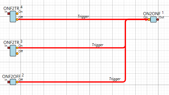
Multiple outputs can be achieved by designing a component with distinct, independent output connections having the same interface type.

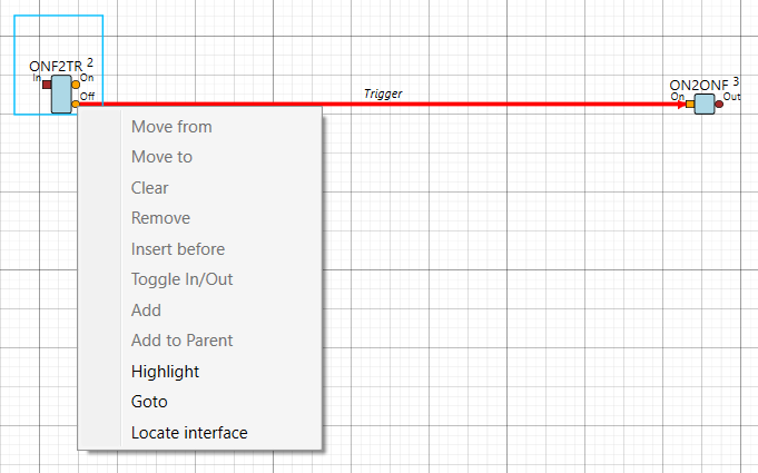
Use the context menu (right mouse click) above an interface connection, like at the Off interface connection in the example at the right.
You can find out the destination of the wire by Highlighting it or use Goto.